17.浮动静态路由
实验需求
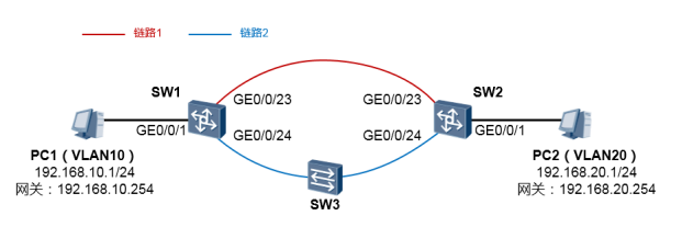
完成SW1及SW2的配置,使得网络正常时PC1与PC2互访的流量走链路2。当SW1与SW3,或SW3 与SW2之间的链路发生故障时,PC1与PC2互访的流量要能够自动切换到链路1。
SW1、SW2首先基于VLAN12运行一个BFD。然后,以SW1为例,配置到达 192.168.2.0/24的静态路由,下一跳为SW2的Vlanif12,将这条静态路由关联BFD。再在SW1上配 置一条浮动的静态路由到达192.168.2.0/24,下一跳为SW2的Vlanif11(将该路由的优先级值调大, 优先级值越小则路由越优)。SW2同理。
SW1的配置如下
[SW1] vlan batch 10 11 12
[SW1] interface gigabitEthernet 0/0/1
[SW1-GigabitEthernet0/0/1] port link-type access
[SW1-GigabitEthernet0/0/1] port default vlan 10
[SW1] interface gigabitEthernet 0/0/23
[SW1-GigabitEthernet0/0/23] port link-type access
[SW1-GigabitEthernet0/0/23] port default vlan 11
[SW1] interface gigabitEthernet 0/0/24
[SW1-GigabitEthernet0/0/24] port link-type access
[SW1-GigabitEthernet0/0/24] port default vlan 12
[SW1] interface Vlanif 10
[SW1-vlanif10] ip address 192.168.10.254 24
[SW1] interface Vlanif 11
[SW1-vlanif11] ip address 192.168.11.1 24
[SW1] interface Vlanif 12
[SW1-vlanif12] ip address 192.168.12.1 24
[SW1] bfd #激活BFD
[SW1-bfd] quit
[SW1] bfd bfd12 bind peer-ip 192.168.12.2 #创建BFD会话bfd12
[SW1-bfd-session-bfd12] discriminator local 1 #对应SW2的remote 1
[SW1-bfd-session-bfd12] discriminator remote 2 #对应SW2的local 2
[SW1-bfd-session-bfd12] commit #注意要使用commit关键字使得BFD生效
#配置静态路由:
[SW1] ip route-static 192.168.20.0 24 192.168.12.2 track bfd-session bfd12
留意到,我们在SW1上配置了两条静态路由,都是去往192.168.20.0/24网段,但是下一跳分别是 SW2的Vlanif12及Vlanif11接口的IP地址。静态路由ip route-static 192.168.20.0 24 192.168.12.2 关联了BFD会话。而静态路由ip route-static 192.168.20.0 24 192.168.11.2 preference 90则将优 先级从缺省的60修改为90,preference关键字指的就是路由的优先级。这使得当BFD检测正常时, SW1的路由表中出现的路由是ip route-static 192.168.20.0 24 192.168.12.2,而当BFD检测失效, 则该条路由也将失效,此时路由表中浮现的路由是ip route-static 192.168.20.0 24 192.168.11.2 preference 90,如此一来就实现了链路的可靠性。SW2同理。
SW2的配置如下
完成上述配置后,我们首先查看一下SW1的路由表:
注意到,此时在路由表中出现的去往192.168.20.0/24的路由,下一跳为192.168.12.2。因此当其收 到发往PC2的流量时,会将流量转发到链路2。 SW2的路由表如下:
从PC1 tracert PC2:
PC>tracert 192.168.20.1
traceroute to 192.168.20.1, 8 hops max
(ICMP), press Ctrl+C to stop
1 192.168.10.254 16 ms 31 ms 1
现在,我们将SW3与SW2之间的连线拉断,如此一来SW1及SW2之间的BFD会立即Down掉,与 之关联的静态路由也将失效。那么SW1及SW2上所配置的浮动静态路由将会浮现在路由表中。 此时SW1的路由表如下
我们看到,浮动路由出现了。SW2同理。 此时从PC1 tracert PC2: