32.MSTP+VRRP的典型组网 | Evergreen Notes
返回首页 32.MSTP+VRRP的典型组网 MSTP+VRRP的典型组网 1.实验拓扑及描述 1. 这是一个由三台交换机组成的倒三角型二层交换网络;网络中有4个VLAN:10、20、30、40; 接口编号如图所示;SW3为接入层交换机,SW1、SW2为汇聚层交换机; 2. VLAN10对应的网段为192.168.10.0/24;VLAN20对
MSTP+VRRP的典型组网
1.实验拓扑及描述
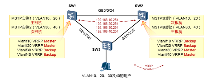
这是一个由三台交换机组成的倒三角型二层交换网络;网络中有4个VLAN:10、20、30、40; 接口编号如图所示;SW3为接入层交换机,SW1、SW2为汇聚层交换机;
VLAN10对应的网段为192.168.10.0/24;VLAN20对应的网段为192.168.20.0/24; VLAN30对应的网段为192.168.30.0/24;VLAN40对应的网段为192.168.40.0/24; 各VLAN的网关均为192.168.x.254的地址,该地址为VRRP组的虚拟地址。
2.实验需求
由于网络中VLAN较多,并且存在二层环路,因此使用MSTP实现环路避免,同时实现负载分 担。要求VLAN10、VLAN20的流量主走SW1-SW3这一侧链路,VLAN30、VLAN40的流量主 走SW2-SW3这一侧链路;
为了提高网络的网关层冗余能力,在SW1及SW2的vlanif10、vlanif20、vlanif30、vlanif40上部 署VRRP,一共4组。
3.现步骤及配置
由于网络中VLAN较多,并且存在二层环路因此使用MSTP实现环路避免,同时实现负载分担。将 VLAN10、20映射到MSTP实例1;将VLAN30、40映射到MSTP实例2。MSTP实例1阻塞掉的端口 为SW3的GE0/0/22,实例2阻塞掉的端口为SW3的GE0/0/21。换句话说就是SW1配置为实例1的主 根、实例2的次根,而SW2配置为实例2的主根、实例1的次根。
这个案例中必须确保VRRP的Master及Backup与MSTP的主、备根重叠。也就是说SW1是MSTP实 例1的主根,同时它是vlanif10及vlanif20的VRRP Master,而SW2是MSTP实例2的主根,同时它是 vlanif30及vlanif40的VRRP Master。
SW3的配置如下:
#在SW3上创建VLAN,并将接口加入相应的VLAN:
[SW3] vlan batch 10 20 30 40
[SW3] interface GigabitEthernet0/0/21
[SW3-GigabitEthernet0/0/21] port link-type trunk
[SW3-GigabitEthernet0/0/21] port trunk allow-pass vlan 10 20 30 40
[SW3] interface GigabitEthernet0/0/22
[SW3-GigabitEthernet0/0/22] port link-type trunk
[SW3-GigabitEthernet0/0/22] port trunk allow-pass vlan 10 20 30 40

……忽略连接终端PC的其他接口的配置

#配置MSTP,将vlan10 20映射到实例1,将vlan30 40映射到实例2。在SW3上,MSTP实例1及实例2的优先级
保持默认32768:
[SW3] stp mode mstp
[SW3] stp region-configuration
[SW3-mst-region] region-name huawei   #配置MSTP域名
[SW3-mst-region] instance 1 vlan 10 20   #将VLAN10、20映射到实例1
[SW3-mst-region] instance 2 vlan 30 40   #将VLAN30、40映射到实例2
[SW3-mst-region] active region-configuration #激活配置
[SW3-mst-region] quit
[SW3] stp enable
SW1的配置如下:
SW2的配置如下:
完成配置后,各VLAN的用户都能够ping通自己的网关,在SW3上看看:
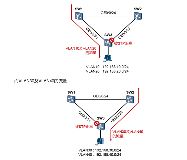
在SW3上我们看到,MSTP实例1中被Block掉的端口是GE0/0/22口;MSTP实例2中被Block掉的端 口是GE0/0/21,符合需求。再去SW1上看看VRRP组的状态:
从上述输出可以看出,SW1为VRRP组10及组20的Master,同时也为VRRP组30和组40的Backup
而SW2则正好相反。
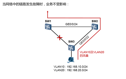
如此一来,VLAN10及VLAN20用户访问外网的流量将按图示的路径转发:
[SW1] vlan batch 10 20 30 40
[SW1] interface GigabitEthernet0/0/24
[SW1-GigabitEthernet0/0/24] port link-type trunk
[SW1-GigabitEthernet0/0/24] port trunk allow-pass vlan 10 20 30 40
[SW1] interface GigabitEthernet0/0/21
[SW1-GigabitEthernet0/0/21] port link-type trunk
[SW1-GigabitEthernet0/0/21] port trunk allow-pass vlan 10 20 30 40

#配置MSTP,将VLAN10 20映射到实例1,将VLAN30 40映射到实例2。将SW1的MSTP设置为实例1的主根,实
例2的次根:
[SW1] stp mode mstp
[SW1] stp region-configuration
[SW1-mst-region] region-name huawei
[SW1-mst-region] instance 1 vlan 10 20
[SW1-mst-region] instance 2 vlan 30 40
[SW1-mst-region] active region-configuration
[SW1-mst-region] quit
[SW1] stp instance 1 root primary
[SW1] stp instance 2 root secondary
[SW1] stp enable

#配置vlanif10、vlanif20、vlanif30、vlanif40,分别加入VRRP组10,20,30,40。其中SW1为VRRP组
10及20的Master,为组30及40的Backup:
[SW1] interface Vlanif 10
[SW1-vlanif10] ip address 192.168.10.253 255.255.255.0
[SW1-vlanif10] vrrp vrid 10 virtual-ip 192.168.10.254
[SW1-vlanif10] vrrp vrid 10 priority 120
[SW1] interface Vlanif 20
[SW1-vlanif20] ip address 192.168.20.253 255.255.255.0
[SW1-vlanif20] vrrp vrid 20 virtual-ip 192.168.20.254
[SW1-vlanif20] vrrp vrid 20 priority 120
[SW1] interface Vlanif 30
[SW1-vlanif30] ip address 192.168.30.253 255.255.255.0
[SW1-vlanif30] vrrp vrid 30 virtual-ip 192.168.30.254
[SW1] interface Vlanif 40
[SW1-vlanif40] ip address 192.168.40.253 255.255.255.0
[SW1-vlanif40] vrrp vrid 40 virtual-ip 192.168.40.254
[SW2] vlan batch 10 20 30 40
[SW2] interface GigabitEthernet0/0/24
[SW2-GigabitEthernet0/0/24] port link-type trunk
[SW2-GigabitEthernet0/0/24] port trunk allow-pass vlan 10 20 30 40
[SW2] interface GigabitEthernet0/0/22
[SW2-GigabitEthernet0/0/22] port link-type trunk
[SW2-GigabitEthernet0/0/22] port trunk allow-pass vlan 10 20 30 40

#配置MSTP,将VLAN10 20映射到实例1,将VLAN30 40映射到实例2。将SW2的MSTP设置为实例2的主根,实
例1的次根:
[SW2] stp mode mstp
[SW2] stp region-configuration
[SW2-mst-region] region-name huawei
[SW2-mst-region] instance 1 vlan 10 20
[SW2-mst-region] instance 2 vlan 30 40
[SW2-mst-region] active region-configuration
[SW2-mst-region] quit
[SW2] stp instance 1 root secondary
[SW2] stp instance 2 root primary
[SW2] stp enable

#配置vlanif10、vlanif20、vlanif30、vlanif40,分别加入VRRP组10,20,30,40。其中SW1为VRRP组
30及40的Master,为组10及20的Backup
[SW2] interface Vlanif 10
[SW2-vlanif10] ip address 192.168.10.252 255.255.255.0
[SW2-vlanif10] vrrp vrid 10 virtual-ip 192.168.10.254
[SW2] interface Vlanif 20
[SW2-vlanif20] ip address 192.168.20.252 255.255.255.0
[SW2-vlanif20] vrrp vrid 20 virtual-ip 192.168.20.254
[SW2] interface Vlanif 30
[SW2-vlanif30] ip address 192.168.30.252 255.255.255.0
[SW2-vlanif30] vrrp vrid 30 virtual-ip 192.168.30.254
[SW2-vlanif30] vrrp vrid 30 priority 120
[SW2] interface Vlanif 40
[SW2-vlanif40] ip address 192.168.40.252 255.255.255.0
[SW2-vlanif40] vrrp vrid 40 virtual-ip 192.168.40.254
[SW2-vlanif40] vrrp vrid 40 priority 120
[SW3] display stp brief
 MSTID  Port                        Role   STP State    Protection
   0    GigabitEthernet0/0/1      DESI   FORWARDING       NONE
   0    GigabitEthernet0/0/2      DESI   FORWARDING       NONE
   0    GigabitEthernet0/0/21     DESI   FORWARDING       NONE
   0    GigabitEthernet0/0/22        DESI   FORWARDING       NONE
   1    GigabitEthernet0/0/1         DESI   FORWARDING       NONE
   1    GigabitEthernet0/0/21        ROOT   FORWARDING       NONE
   1    GigabitEthernet0/0/22       ALTE   DISCARDING       NONE
   2    GigabitEthernet0/0/2         DESI   FORWARDING       NONE
   2    GigabitEthernet0/0/21       ALTE   DISCARDING       NONE
   2    GigabitEthernet0/0/22       ROOT   FORWARDING       NONE
[SW1] display vrrp brief
VRID   State         Interface      Type      Virtual IP      ----------------------------------------------------------------------------------
10      Master        Vlanif10      Normal    192.168.10.254
20      Master        Vlanif20        Normal    192.168.20.254
30      Backup        Vlanif30       Normal    192.168.30.254
40      Backup       Vlanif40        Normal    192.168.40.254  ----------------------------------------------------------------------------------
Total:4     Master:2     Backup:2     Non-active:0
[SW2]display vrrp brief
VRID  State        Interface                Type     Virtual IP      ----------------------------------------------------------------
10    Backup       Vlanif10                 Normal   192.168.10.254
20    Backup       Vlanif20                 Normal   192.168.20.254
30    Master       Vlanif30                 Normal   192.168.30.254
40    Master       Vlanif40                 Normal   192.168.40.254  ----------------------------------------------------------------
Total:4     Master:2     Backup:2     Non-active:0